

How to Install Quickshifter Sensor Systems

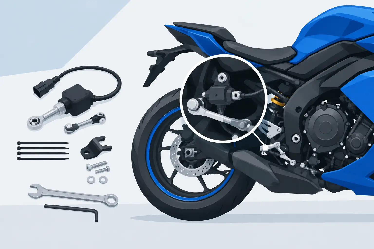
A quickshifter only performs as well as the signal it receives. Learn how to install quickshifter sensor hardware correctly and you get clean, repeatable clutchless upshifts under load. Install it with the wrong rod direction, preload, or wiring route and the system may miss shifts, cut at the wrong time, or leave you chasing a problem that is entirely mechanical.
This is a precision job, not a universal bolt-on procedure. Sensor style, shift pattern, rearset design, ECU strategy, and whether your motorcycle uses a push or pull linkage all affect the final setup. Start with the instructions supplied by the quickshifter and your motorcycle-specific harness, then use this guide to confirm the critical details before the bike goes back on track.
Confirm Fitment Before You Install the Sensor
A quickshifter sensor is normally fitted into the shift linkage between the shift lever and transmission shift arm. On most sport bikes, it replaces a section of the existing shift rod or is supplied as part of a model-specific rod assembly. The sensor detects compression or tension as you apply pressure to the shift lever, then signals the ECU or quickshifter module to briefly interrupt ignition, fuel, or both.
Before removing anything, confirm that the sensor matches your system. Some sensors work only with a specific standalone controller, while others connect directly to an OEM ECU or an aftermarket ECU through a dedicated harness. A sensor may also be compression-only, tension-only, or bidirectional. Using the wrong type for your linkage direction is one of the most common installation errors.
Check these four points before you begin:
- Your motorcycle’s exact make, model, year, and ECU or quickshifter compatibility
- The shift pattern you will run: standard or reverse/race shift
- Whether the linkage loads the sensor in push/compression or pull/tension during an upshift
- The thread direction and pitch at both ends of the shift rod
Do not assume that a sensor designed for a similar model will have the correct connectors, rod length, or thread adapters. Fitment-specific electronics and linkage hardware remove guesswork and are worth the investment on a race-prepared bike.
Tools and Preparation
Put the motorcycle on a secure rear stand with the transmission in neutral and the ignition switched off. If you will be plugging into the ECU, disconnect the negative battery terminal first. Photograph the existing linkage before disassembly. That quick reference can save time if your rearsets use offset hardware, rose joints, or an unconventional routing path.
You will typically need open-end wrenches for the shift rod locknuts, a torque wrench where access permits, the correct Allen or socket tools for the rearset hardware, threadlocker if specified by the rearset or sensor manufacturer, and zip ties or P-clips for wire management. Keep a ruler or caliper nearby to record the original shift rod length.
Clean the linkage area before installation. Grit around the rose joints or transmission shift arm can make it harder to identify play and can contaminate threaded components while you work.
Remove the Original Shift Rod Carefully
Mark the relationship between the shift arm and its shaft with a paint pen if the shift arm must come off. On many motorcycles, the sensor installation requires only removal of the shift rod, not the shift arm itself. Leave the arm in place unless the supplied instructions call for a different configuration.
Loosen the locknuts at each end of the original rod. Remember that one end may use left-hand threads. Forcing a left-hand-thread locknut in the usual direction can damage the rod end or sensor adapter. Once loose, count the exposed threads or measure the rod assembly from center to center. This gives you a reliable baseline for pedal position when installing the new sensor.
Inspect the rose joints while they are accessible. Any notchiness, excessive radial play, bent stud, or damaged boot deserves attention now. A quickshifter cannot compensate for worn linkage hardware. Free, accurate movement at the lever is part of a consistent shift cut.
How to Install a Quickshifter Sensor in the Linkage
Install the sensor so its load direction matches the way your bike shifts upward. This is the detail that determines whether the system triggers when you command an upshift or remains inactive.
With a standard shift pattern, the rider lifts the shift lever for an upshift. With reverse shift, the rider presses it down. Depending on rearset geometry and the location of the transmission shift arm, either action can place the sensor under compression or tension. Do not decide based on lever movement alone. Watch the linkage itself as the lever is moved through an upshift motion.
Most sensors are marked with arrows, a push/pull indication, or a defined installation orientation. Follow those markings and the manufacturer’s documentation. If you are using a bidirectional sensor, orientation can be less restrictive electrically, but correct mechanical positioning and adequate clearance still matter.
Thread the supplied adapters and rod ends into the sensor by hand. Engage enough thread to meet the manufacturer’s minimum engagement requirement, while leaving room to adjust pedal height. Avoid running the joints too close to the end of their threads. A linkage that looks correct in the paddock can flex or strip under aggressive track use if thread engagement is insufficient.
Set the assembled rod to approximately the original center-to-center length. Reconnect it to the shift lever and transmission arm without fully tightening the locknuts. Move the lever through its full travel by hand and verify that the sensor body, adapters, rod ends, and wire exit have clearance from the frame, engine cases, chain, sprocket cover, and rearset components.
The sensor must not bottom out, bind, or become a structural stop at either end of shift lever travel. If clearance is tight, adjust rod length, rearset lever position, or the supplied adapter arrangement as allowed by the kit. Never bend the sensor or force the wiring lead into a sharp angle to make it fit.
Once pedal position and free movement are correct, tighten the linkage fasteners and locknuts to the specifications provided for the hardware. Hold the sensor body with the appropriate wrench flats while tightening locknuts. Do not use the wiring lead as a handle, and do not twist the sensor housing against the cable.
Route the Harness for Race-Ready Reliability
Route the sensor wire along the existing harness path where possible, keeping enough slack for engine movement and full suspension travel. The wire should not pull tight when the motorcycle is leaned onto the side stand, compressed on the rear stand, or moved from lock to lock if its path runs near the steering head.
Keep the harness away from the chain, front sprocket, exhaust headers, radiator fan, and sharp edges around the frame or rearsets. Secure it at intervals with quality zip ties, but do not cinch them hard enough to crush the cable. A small service loop near the sensor prevents the wire from carrying stress as the linkage moves.
Connect the sensor to the correct quickshifter module or ECU harness. Connector colors are not a substitute for the wiring diagram. On programmable systems, ensure the input is assigned to the quickshifter channel rather than an auxiliary switch or data input.
Configure the Shift Cut Before the First Ride
A correctly mounted sensor still needs correct electronic settings. At minimum, verify sensor polarity or load direction, activation threshold if your system offers one, minimum RPM, throttle position requirement, and cut time.
Start with the manufacturer’s recommended base map or cut time for your engine configuration. A high-revving inline-four, a large-displacement twin, and a heavily modified race engine can respond differently. Too short a cut can create a harsh or incomplete shift. Too long a cut can feel lazy, upset chassis balance, and cost acceleration between corners.
Do not set the activation threshold so low that vibration or a resting boot triggers the system. Set it too high, however, and you may have to apply excessive lever force before the cut occurs. The goal is a deliberate shift command with no false activation.
With the rear wheel safely off the ground, use the system’s diagnostic function if available to confirm that lever pressure is recognized in the correct direction. Some ECUs display a live sensor value, while standalone modules may use an LED or setup mode. This static test confirms the sensor and harness signal, but it does not replace a controlled road or track test.
Test Under Load and Recheck the Linkage
For the first ride, warm the engine fully and test the quickshifter in a controlled environment. Use moderate throttle and midrange RPM first. Keep your foot clear of the lever between shifts. Resting pressure on the lever can preload the sensor and lead to inconsistent operation.
A clean shift should feel positive and fast, without a false neutral, drivetrain clunk, or prolonged power interruption. If the system cuts but the gear does not engage, inspect linkage adjustment before changing electronics. If it does not cut at all, confirm sensor direction, connector seating, ECU settings, and minimum RPM or throttle thresholds.
After the first heat cycle and initial test session, inspect the sensor body, locknuts, rose joints, and cable ties again. Race vibration finds loose hardware quickly. This final check is where a careful installation becomes a dependable performance upgrade.
A properly installed quickshifter is not about making every street shift effortless. It is about preserving chassis stability and keeping the motorcycle driving forward when the pace is high. Match the sensor to the bike, set the linkage without compromise, and validate the cut before asking the system to perform at race speed.